TOFD testing for welds, components and systems – precise, fast and documented.

TOFD - Time-of-Flight Diffraction

TOFD testing for welds, components and systems – precise, fast and documented.

Request quote
  • Precise crack localization & defect evaluation
  • Complementary to Ultrasonic Testing (UT)
  • Combinable with Phased Array

Complementary UT Method

TOFD (Time-of-Flight Diffraction)

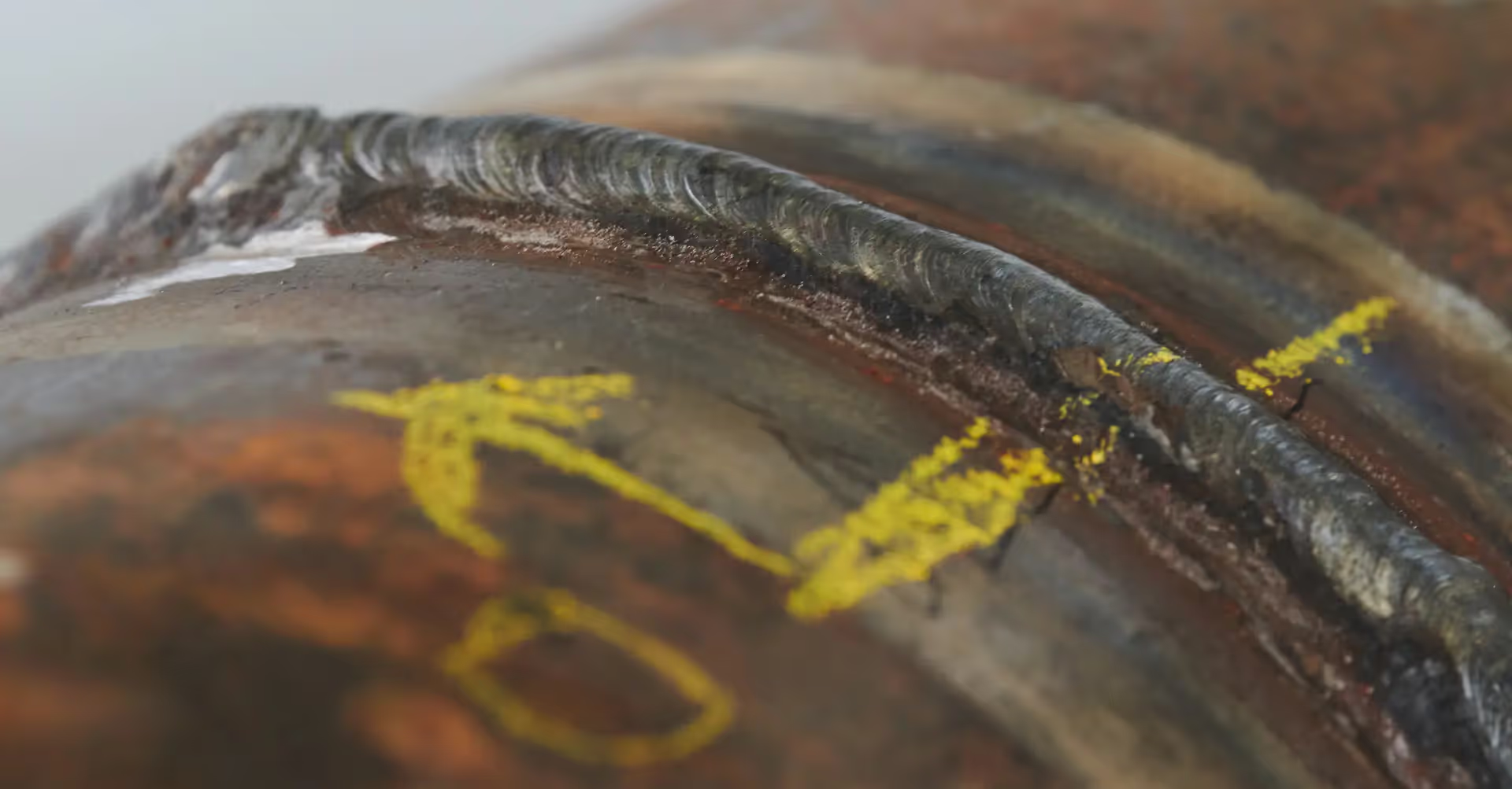
The TOFD method (Time-of-Flight Diffraction) is a highly precise technique of non-destructive ultrasonic testing (UT). It is used by Zeros GmbH especially for weld inspection to accurately locate cracks and bonding defects and to measure their extent.

Unlike classical pulse-echo testing, TOFD utilizes the diffraction of sound waves at crack tips. This allows defects to be detected regardless of their orientation – a decisive advantage for complex weld geometries or thick wall sections.

Advantages of the TOFD Method
  • High sensitivity in crack detection
  • Precise measurement of crack height and depth
  • Low dependency on defect orientation
  • Ideal combination with Phased Array technology
  • Fast data acquisition with digital recording
  • No radiation protection requirements as with RT
Application Areas
  • Weld inspection on pressure vessels, pipelines and power plant components
  • Quality assurance in manufacturing and maintenance
  • Evaluation of cracks, bonding defects and notches
  • Large components with thick walls
Testing Principle

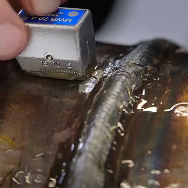
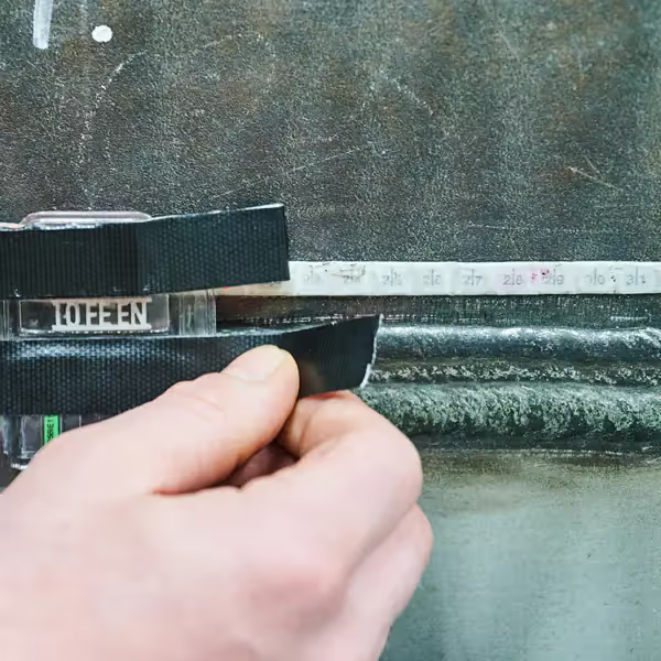
In the TOFD method, two probes are positioned opposite each other along the weld seam. One probe emits an ultrasonic pulse while the receiver captures both the flight time of reflections and diffracted waves. From these signals, a precise image of the defect position in depth and size is created – fully documented and evaluable.

As an accredited testing service provider according to DIN EN ISO/IEC 17025, Zeros GmbH performs TOFD inspections on-site at construction sites or stationary in the testing laboratory – including standardized reporting and result evaluation.

Further information about ultrasonic testing can be found on our main page Ultrasonic Testing (UT).

Procedures and applications in the field of Ultrasonic Testing

Related Procedures & Applications

Ultrasonic testing with state-of-the-art technology and precision

FAQ

Frequently Asked Questions

What is Zeros GmbH?

Zeros GmbH is an independent testing laboratory for destructive and non-destructive materials testing. We support companies from incoming inspection to series release – including digital test reports and full traceability.

We operate under accreditation to DIN EN ISO/IEC 17025 (quality management for laboratories). See our current accreditation information here.

Which standards is Zeros accredited to?

We are accredited by DAkkS to DIN EN ISO/IEC 17025. This standard ensures that test methods, equipment control, personnel qualification and reporting meet the highest requirements.

An overview of services and scopes is available on our homepage.

What services does Zeros GmbH offer?

Our portfolio covers NDT (UT, RT, MT, PT, VT), mechanical testing (tensile, hardness, Charpy), metallography (microstructure, grain size, coating thickness) and chemical analysis (e.g. OES, XRF). We also provide specimen preparation, documentation and consulting.

How can I use Zeros services?

Please contact us by email or use the contact option on the website. Share material, standard/specification and quantity – we'll get back to you promptly with a solution.

Technical Functionality of TOFD Testing

How does TOFD Ultrasonic Testing work?

TOFD Principle Signal Course

In the TOFD method (Time-of-Flight Diffraction), two ultrasonic probes (transmitter and receiver) are positioned opposite each other on the weld seam. The transmitter emits short pulses through the material, and the receiver records the incoming signals.

Unlike the classical pulse-echo method, TOFD is not based on reflected echoes but on the diffraction of sound waves at the tips of defects, e.g., cracks. By precisely measuring the time differences of these diffracted waves, the exact depth and height of a defect can be calculated.

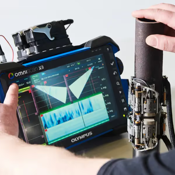
The result is a time-resolved signal diagram displayed as a grayscale image (B-Scan). This shows the crack tips and the base material as characteristic lines, allowing an experienced inspector to reliably detect and evaluate cracks.

Advantageously, TOFD operates independently of defect orientation, offers high repeatability, and enables comprehensive documentation through digital recording.

Signals in TOFD Testing

The following overview shows the most important signals recorded in TOFD ultrasonic testing and their significance for defect evaluation.

Signal Type Origin Interpretation / Meaning
Lateral Wave Direct path along the surface between transmitter and receiver Reference signal – used for time calibration
Upper Diffracted Wave Diffraction at the upper tip of a crack Upper crack start visible in the B-Scan
Lower Diffracted Wave Diffraction at the lower tip of a crack Lower crack end, enables depth determination
Back Wall Echo Reflection from the opposite component surface Shows material thickness, possibly shadowed by defects